TRAM50 - Elsycom
Radio > AM
Adcom - Elsycom
New
Available in 60 days
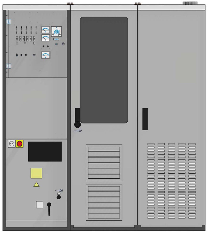
50 kW Solid State MF Broadcast Transmitter
Amplifier
The amplifier section of the transmitter has one 50 kW power block equipped with 48 power modules. This power
module is the basic unit of the RF amplifier. It supplies somewhat more than 1 kW into a special series transformer
assembly (doughnut combiner) which summarises the power of all 48 power modules to the total transmitter power of
50 kW.
The module is designed as one single printed circuit board, which is plugged into the assembly. The module comprises
a switched RF amplifier bridge and an associated PDM modulator. Each unit supplies a completely modulated RF
signal into the combining transformer. Thus in case of a module fault the service is maintained with only slightly reduced
power but without reduction of quality performance.
RF Output Filter
The 50 kW power block has an RF output filter which is contained in one 19" cabinet.
The transmitter is factory equipped for and tuned on the determined operation frequency. The coils of the output circuit
can be tuned for the whole MF band, while the capacitors are determined for sub-ranges of this frequency band.
Drive and Signal Processing
The transmitter is equipped with a common drive unit (PLL synthesizer) and a common PDM processing unit for all
power modules. A dual synthesizer assembly in passive standby configuration is available as an option. The RF drive
can also be switched to an external frequency generator or synchronised from an external standard.
Power Supply
A common power supply, comprising a 400 V to 210 V three-phase transformer and two three-phase rectifier units, is
provided for the 50kW power block. Each rectifier unit is fed from an independent phase-shifted 210 V transformer
output. This feeding provides 12-pulse ripple, only. The 400 V / 230 V feed also supplies the auxiliary equipment.
In the standard configuration, the transformer is contained in the bottom of the amplifier cabinet. As an option, we also
provide a solution where the transformer is located externally from the transmitter.
Cooling
The components of the whole transmitter are basically air-cooled. A fan assembly located below the 50 kW power block
moves the cooling air along the heat sinks of the power modules. This fan assembly compensates only the pressure
drop inside the amplifier cabinet. The air is taken from the room and will be exhausted into the room.
Should external air ducts be required, an additional external blower system is needed to compensate the pressure drop
in the external air ducts. Layout of the external air cooling system depends on the individual conditions at site.
Control Section
The control section of the transmitterc omprises the 400 V / 230 V mains input, the internal distribution, the control
panel with the components for local control and for metering as well as the remote-control interface. Furthermore, it
comprises the common drive unit (PLL synthesizer) and the AF input unit with PDM processing


